> ## Documentation Index
> Fetch the complete documentation index at: https://docs.aseeflow.org/llms.txt
> Use this file to discover all available pages before exploring further.

# Plan Item Lifecycles

CMMN case instances and plan items go through a lifecycle of states during their execution. Depending on their state, different actions may be carried out to interact with them. Moreover, state transitions may automatically trigger changes in other plan items. The concrete lifecycle of a plan item depends on its plan item definition.

The following descriptions cover the CMMN lifecycles as supported by the ASEE Flow engine. This is a subset of states and transitions that the CMMN standard defines. Any state or transition that is currently not supported is marked in grey.

The descriptions in this section are general for the constructs they describe. Considerations that are specific for individual plan item definitions can be found in the respective sections of this guide.

## Lifecycles By Example

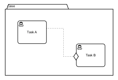
To understand the role lifecycles play for CMMN execution, consider the following case:

<img src="https://mintcdn.com/aseeflow/OpLRJy6TPnBLn55c/reference/cmmn11/concepts/img/example-lifecycle-case.png?fit=max&auto=format&n=OpLRJy6TPnBLn55c&q=85&s=2ab1d46e6752dd3e8ab19ba2ba917b62" alt="" width="395" height="267" data-path="reference/cmmn11/concepts/img/example-lifecycle-case.png" />

This case contains two human tasks *Task A* and *Task B* that are connected by a sentry. The sentry expresses that Task B can be enacted when Task A finishes. This is formally specified by lifecycles. In our example, the following steps might take place:

1. A user instantiates the case by `caseService.createCaseInstanceByKey("case");`. A new case instance is created in state `ACTIVE`.
2. Two instances for each human task are automatically created, both in state `AVAILABLE`.
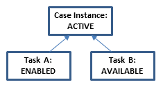
3. Task A does not have a condition to start, so it immediately reaches state `ENABLED`. Note that the steps 1 to 3 all happens synchronously with the `caseService` invocation from step 1. The case is now in the following state:
   \<center>
   <img src="https://mintcdn.com/aseeflow/EOmYJq0E21aelwRy/reference/cmmn11/concepts/img/lifecycle-example-1.png?fit=max&auto=format&n=EOmYJq0E21aelwRy&q=85&s=e912fecf158fb5fa1caa564f1f7e8888" alt="" width="235" height="129" data-path="reference/cmmn11/concepts/img/lifecycle-example-1.png" />
   \</center>
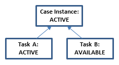
4. A user manually starts Task A by calling `caseService.manuallyStartCaseExecution(taskAExecutionId);`. As a consequence, Task A reaches state `ACTIVE` and a task instance is added to the assignee's task list. Note that starting a task is only allowed if that task is in state `ENABLED`. Thus, trying to manually start Task B here by `caseService.manuallyStartCaseExecution(taskBExecutionId);` would fail. The state is now:
   \<center>
   <img src="https://mintcdn.com/aseeflow/EOmYJq0E21aelwRy/reference/cmmn11/concepts/img/lifecycle-example-2.png?fit=max&auto=format&n=EOmYJq0E21aelwRy&q=85&s=ff1a017ad98d5eda022ba4468fa96f4f" alt="" width="235" height="129" data-path="reference/cmmn11/concepts/img/lifecycle-example-2.png" />
   \</center>
5. The assignee completes the task instance by calling `taskService.complete(taskId);`. Task A reaches the state `COMPLETED`.
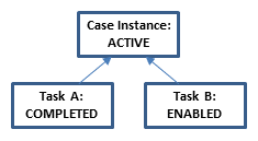
6. Task A's state transition triggers Task B's sentry. In consequence, Task B becomes `ENABLED`. This happens synchronously in the invocation from step 5. Accordingly, the case's new state is:
   \<center>
   <img src="https://mintcdn.com/aseeflow/EOmYJq0E21aelwRy/reference/cmmn11/concepts/img/lifecycle-example-3.png?fit=max&auto=format&n=EOmYJq0E21aelwRy&q=85&s=be3041f86ed68441494d65ec7e4bd710" alt="" width="235" height="129" data-path="reference/cmmn11/concepts/img/lifecycle-example-3.png" />
   \</center>
7. Similar to Task A, a user may now use the `CaseService` and `TaskService` to start Task B, complete the corresponding task instance, and complete Task B. Ultimately, Task B reaches the state `COMPLETED`.
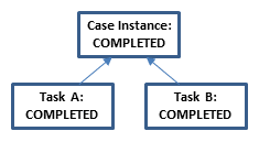
8. With both tasks in state `COMPLETED`, the case instance automatically reaches the state `COMPLETED` as well. The state has case has reached the following state:
   \<center>
   <img src="https://mintcdn.com/aseeflow/EOmYJq0E21aelwRy/reference/cmmn11/concepts/img/lifecycle-example-4.png?fit=max&auto=format&n=EOmYJq0E21aelwRy&q=85&s=87750aaefa7d7d4b066ffbc78d6a0e3a" alt="" width="235" height="129" data-path="reference/cmmn11/concepts/img/lifecycle-example-4.png" />
   \</center>
9. A user may close the case instance by invoking `caseService.closeCaseInstance(caseInstanceId);`. The case instance reaches the state `CLOSED`.

Notice how the lifecycle states define the overall state of the case and restrict the interactions that are possible. For example, the tasks A and B can only be worked on when in state `ACTIVE`. Before, they go through states `AVAILABLE` and `ENABLED`, which represent that conditions for working on the task are not yet met, for example that the task was not manually started or that a sentry is not fulfilled yet.

This formal lifecycle model is exposed via the `CaseService` API in ASEE Flow. Not only is it possible to trigger state transitions as in the code examples above. By making a case instance or case execution query, the current lifecycles state of a plan items are exposed. For example, the following code gets the state of the plan item for Task A:

```java theme={null}
CaseExecution caseExecution = caseService.createCaseExecutionQuery().activityId("taskA").singleResult();
caseExecution.isAvailable();
caseExecution.isActive();
caseExecution.isCompleted();
...
```

Note that a `CaseExecution` object corresponds to a plan item, here the plan item for Task A.

## Case Instance Lifecycle

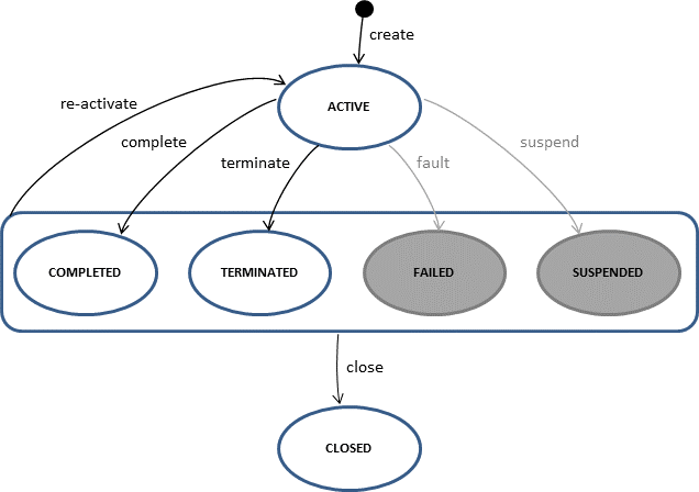
*Case instance* refers to an instance of the case plan model. More specific, it is an instance of the single top-level stage in a case definition. The lifecycle of a case instance is the following:

<img src="https://mintcdn.com/aseeflow/OpLRJy6TPnBLn55c/reference/cmmn11/concepts/img/CaseInstanceLifecycle.png?fit=max&auto=format&n=OpLRJy6TPnBLn55c&q=85&s=7c73aea7e2acf7fd5dfbb5efc3a2022a" alt="" width="636" height="448" data-path="reference/cmmn11/concepts/img/CaseInstanceLifecycle.png" />

States:

<table class="table table-striped">
  <tr> <th>State</th> <th>Description</th> </tr>
  <tr> <td> active </td> <td> The state <i>active</i> is the initial state when a case is instantiated via the <code>CaseService</code> API. Subsequently, all plan items defined in the case plan model are created and enter the state <i>available</i>. </td> </tr>
  <tr> <td> completed </td> <td> The transition <i>complete</i> automatically triggers when all plan items contained in the case plan model are completed, terminated, or disabled.  With automatic completion enabled, only required plan items have to reach theses states. Furthermore, it is possible to manually complete a case instance via the <code>CaseService</code> API if it has no active tasks or stages and all required plan items are either completed, terminated, or disabled. </td> </tr>
  <tr> <td> terminated </td> <td> The transition <i>terminate</i> automatically triggers when the case instance's exit criteria are fulfilled. Furthermore, it is possible to manually terminate an <i>active</i> case instance via the <code>CaseService</code> API. </td> </tr>
  <tr> <td> closed </td> <td> A case instance can be manually closed at any time via the <code>CaseService</code> API. This removes the case instance from the runtime database. </td> </tr>
</table>

## Task/Stage Lifecycle

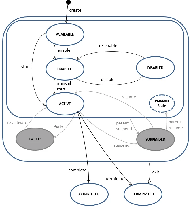
The lifecycle of a task or stage plan item is the following:

<img src="https://mintcdn.com/aseeflow/OpLRJy6TPnBLn55c/reference/cmmn11/concepts/img/TaskStageLifecycle.png?fit=max&auto=format&n=OpLRJy6TPnBLn55c&q=85&s=f2f37b3c2cc9c89957182793d2d35617" alt="" width="670" height="726" data-path="reference/cmmn11/concepts/img/TaskStageLifecycle.png" />

States:

<table class="table table-striped">
  <tr> <th>State</th> <th>Description</th> </tr>
  <tr> <td> available </td> <td> A task/stage becomes available as soon as the stage it is contained in becomes active. </td> </tr>
  <tr> <td> enabled </td> <td> A task or stage becomes <i>enabled</i> as soon as any of its entry criteria is fulfilled. If this is given when a the task/stage becomes available, it immediately becomes enabled or, depending on its manual activation rule, active. </td> </tr>
  <tr> <td> disabled </td> <td> A task or stage can be disabled by using the <code>CaseService</code> API. While an <i>enabled</i> task prevents the containing stage from completion, disabling contained tasks is one way of making a stage completable. Similarly, a disabled task/stage can be re-enabled using the <code>CaseService</code> API. </td> </tr>
  <tr> <td> active </td> <td> When a task or stage becomes active, its actual work is performed. For a stage, all contained plan items are instantiated. For a task, its actual work is issued, e.g., for a human task, a task instance is created and needs to be worked on by a user. In order for a task or stage to become active, at least one entry criterion has to be fulfilled. Activation can either be performed manually by a human worker using the <code>CaseService</code> API if the manualActivation rule is specified or automatically if not manualActivation rule is specified. </td> </tr>
  <tr> <td> completed </td> <td> The <i>complete</i> transition triggers for a task when its actual work is done. For a stage, this transition triggers when all contained tasks/stages are either completed, terminated, or disabled. With automatic completion enabled, only required plan items have to reach theses states. A task/stage in state <i>completed</i> is removed from the runtime database. </td> </tr>
  <tr> <td> terminated </td> <td> The <i>exit</i> transition triggers when the task's/stage's exit criteria are met or when the parent (Case instance or a stage) is terminated. Furthermore, it is possible to manually terminate an <i>active</i> stage/task via the <code>CaseService</code> API. A task/stage in state <i>terminated</i> is removed from the runtime database. </td> </tr>
</table>

## Milestone Lifecycle

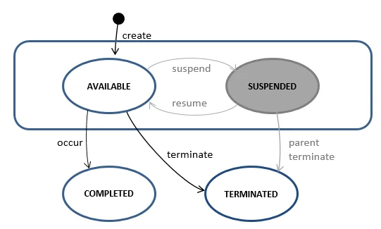
The lifecycle of a milestone plan item is the following:
<img src="https://mintcdn.com/aseeflow/OpLRJy6TPnBLn55c/reference/cmmn11/concepts/img/MilestoneLifecycle.png?fit=max&auto=format&n=OpLRJy6TPnBLn55c&q=85&s=8c28d4656d35477c6770a535a575fc62" alt="" width="541" height="325" data-path="reference/cmmn11/concepts/img/MilestoneLifecycle.png" />

States

<table class="table table-striped">
  <tr> <th>State</th> <th>Description</th> </tr>
  <tr> <td> available </td> <td> A milestone becomes available as soon as the stage it is contained in becomes active. </td> </tr>
  <tr> <td> completed </td> <td> The transition <i>occur</i> automatically triggers when all entry criteria of the milestone are fulfilled. </td> </tr>
  <tr> <td> terminated </td> <td> It is possible to manually terminate an <i>available</i> milestone via the <code>CaseService</code> API. A task/stage in state <i>terminated</i> is removed from the runtime database. </td> </tr>
</table>